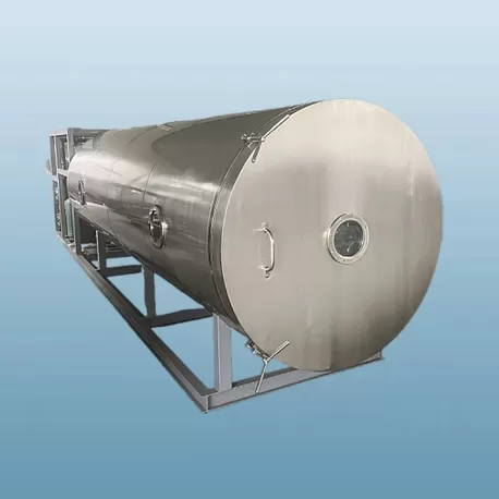
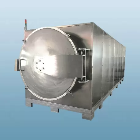
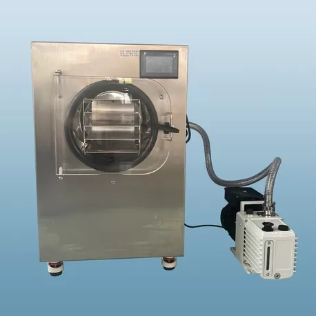
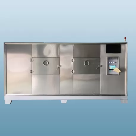
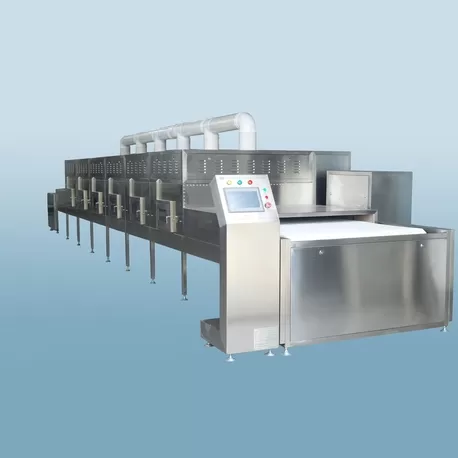
Dehydration processes in industrial manufacturing dictate overall production efficiency, product quality, and energy consumption. Traditional drying methodologies, such as hot air convection, spray drying, and freeze drying, rely on thermal conduction and convection to transfer heat from the surface of a material to its core. This external heating mechanism often establishes thermal gradients that can degrade sensitive compounds and limit throughput. To address these operational limitations, dielectric heating offers an alternative approach by generating volumetric heat directly within the damp material. Evaluating the practical implementation of microwave drying requires a deep understanding of electromagnetic-material interactions, structural engineering constraints, and operational economics.
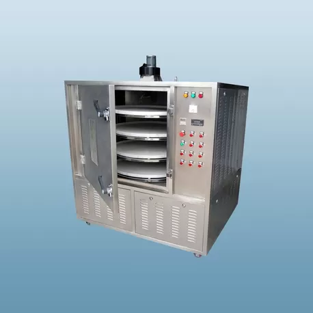
1. The Physics of Electromagnetic-Material Interaction in Microwave Drying
To understand how volumetric heating operates, one must analyze the dielectric properties of the target material. Unlike conventional heating, which depends on temperature differentials, electromagnetic energy couples directly with polarized molecules and free ions within the wet product. This phenomenon is governed by the complex relative permittivity of the material, which represents its ability to store and dissipate electromagnetic energy.
The complex permittivity is mathematically expressed as having a real part, which represents the dielectric constant, and an imaginary part, known as the dielectric loss factor. The dielectric constant measures the ability of the material to polarize in response to an applied electric field, while the loss factor quantifies the efficiency with which the material converts electromagnetic energy into heat. Water possesses a high dielectric constant and loss factor relative to most dry solids. Consequently, when an electromagnetic field of industrial frequency—typically 915 MHz or 2450 MHz—is applied, the water molecules rotate rapidly to align with the alternating field, producing volumetric heat through dipole rotation and ionic conduction.
Another fundamental parameter in system design is the penetration depth. This metric defines the distance at which the power density of the electromagnetic wave decreases to approximately 37% of its value at the boundary surface. Penetration depth is inversely proportional to both the frequency of the wave and the loss factor of the material. For large-scale industrial operations, utilizing a lower frequency like 915 MHz provides deeper penetration compared to 2450 MHz, making it more suitable for bulk materials, thick timber, or deep bed agricultural processing.
2. Addressing Non-Uniform Fields in Microwave Drying Systems
A primary engineering challenge in the deployment of high-power electromagnetic systems is the maintenance of field uniformity. In static cavities, electromagnetic waves can form standing wave patterns, resulting in localized areas of high and low field intensity. These spatial variations often manifest as hot spots and cold spots within the product bed, potentially leading to uneven dehydration or localized thermal degradation.
This phenomenon becomes more complex due to the temperature-dependent nature of dielectric properties. In many materials, as the temperature rises, the dielectric loss factor increases. This behavior creates a thermal feedback loop where hot spots absorb energy at an accelerated rate, causing rapid temperature spikes while surrounding areas remain under-processed. To mitigate this pattern of localized thermal escalation without using high-risk operational profiles, system designers implement several physical and mechanical interventions:
Multi-Port Waveguide Feeds: Introducing electromagnetic energy from multiple locations within the chamber disperses the standing wave patterns, reducing the probability of field concentration.
Mechanical Mode Stirrers: Rotating metallic blades within the cavity continuously alter the boundary conditions, dynamically shifting the electromagnetic hot spots so that the time-average energy distribution remains balanced.
Continuous Conveyor Configurations: Moving the material through the microwave field on a continuous belt ensures that every portion of the product experiences a comparable integrated energy dosage.
Variable Frequency and Phase Tuning: Utilizing advanced solid-state generators allows the system to shift frequencies or modify phases dynamically to compensate for changing material impedances.
Implementing these techniques requires precise cavity geometry and simulation of the electromagnetic wave propagation. By executing these systemic adjustments, industrial operations can maintain product integrity without relying on overly conservative cycle times.
3. Magnetron Reliability and Generator Architecture
The generation of electromagnetic energy relies on magnetrons or solid-state generators, each presenting distinct trade-offs in terms of capital cost, lifespan, and control precision. The magnetron remains the industry workhorse due to its high power-conversion efficiency and lower initial purchase price. However, these vacuum tubes degrade over time, with standard industrial magnetrons typically exhibiting a service life between 4,000 and 8,000 hours depending on operating conditions and cooling efficiency.
Thermal management of the magnetron is a primary determinant of its operational longevity. Industrial facilities must choose between air-cooled and water-cooled generator assemblies. For high-capacity, continuous production environments, water-cooled systems are generally preferred because they dissipate waste heat more effectively, preventing thermal stress on the internal cathode and anode structures. By implementing water-cooled magnetron arrays, systems manufactured by Nasan achieve consistent performance over extended duty cycles, reducing the frequency of unscheduled maintenance events.
An alternative to the traditional magnetron is the solid-state generator. While currently carrying a higher cost per kilowatt of power, solid-state transmitters offer near-infinite operating lifespans and allow for precise adjustments of frequency, phase, and output power. This high degree of control prevents sudden impedance mismatches, which can reflect energy back to the generator and cause hardware degradation. For highly sensitive pharmaceutical applications or high-value organic materials, the gradual shift toward solid-state architecture represents a logical progression in equipment reliability.
4. Sanitary Design and Clean-in-Place Mechanics in Vacuum Chambers
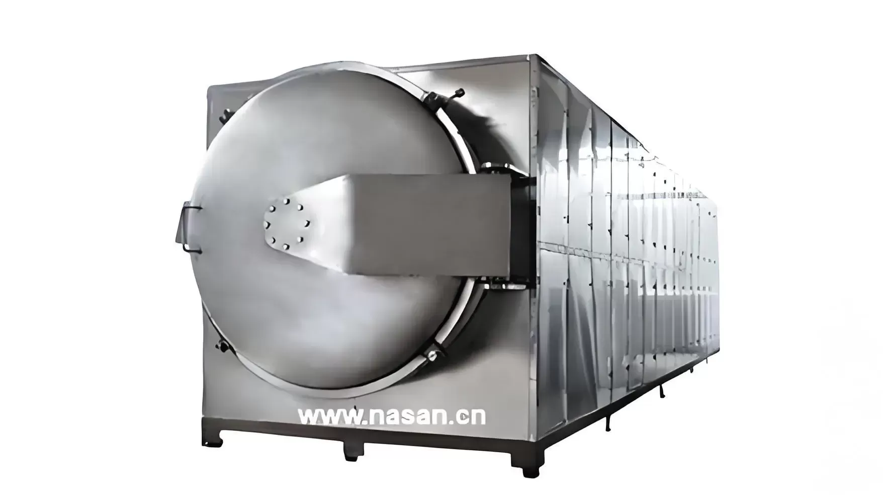
When combining electromagnetic heating with vacuum environments to dry heat-sensitive items at lower boiling points, the design of the chamber becomes highly complex. The integration of vacuum seals, microwave-transparent windows, and internal mechanical supports introduces significant challenges for sanitation and maintenance, particularly in food and pharmaceutical manufacturing where compliance with Good Manufacturing Practice (GMP) guidelines is mandatory.
Vacuum vessels must withstand structural pressure while preventing any electromagnetic radiation leakage. Waveguides that deliver energy into the vacuum chamber must be sealed with low-loss dielectric windows, typically fabricated from high-purity alumina ceramics or polytetrafluoroethylene (PTFE). These windows must remain free of dust, condensation, and product residues. Any accumulation of material on the window surface can cause localized heating, leading to window cracking or electrical arcing inside the chamber.
To sustain sanitary operations, modern processing cavities must incorporate Clean-in-Place (CIP) systems. Designing a CIP system for an electromagnetic vacuum chamber requires several unique considerations:
Self-Draining Cavity Geometries: All internal surfaces must slope toward a central drainage point to prevent pool formation of cleaning solutions.
Retractable Spray Nozzles: Metallic spray balls must either be retracted during operation or positioned in designated field-free pockets to avoid disturbing the electromagnetic field or attracting electrical arcs.
Sanitary Waveguide Seals: The junction between the waveguide window and the chamber wall must be flush, eliminating crevice zones where biological contaminants or bacteria could proliferate.
Addressing these sanitary requirements during the initial engineering phase ensures that facilities can perform rapid product changeovers without compromising regulatory compliance or operational hygiene.
5. Financial Feasibility and Process Economics of Microwave Drying
Evaluating the adoption of electromagnetic drying technology requires a balanced analysis of capital expenditure (CAPEX) against ongoing operational expenditure (OPEX). Industrial dryers utilizing electromagnetic energy generally demand a higher initial investment than steam or direct-fired hot air dryers due to the cost of high-voltage power supplies, magnetrons, waveguides, and shielding systems. Consequently, the financial justification for this investment relies on process-specific efficiency gains, product quality premiums, and footprint reductions.
The operational cost structure is heavily influenced by the efficiency of energy conversion. While gas-fired hot air systems convert fuel energy directly to heat, electromagnetic systems require electrical energy, which is then converted to microwave energy at an efficiency rate of approximately 60% to 70% for magnetrons. However, once the electromagnetic energy is inside the chamber, it targets the water molecules directly, rather than heating the surrounding air, chamber walls, or conveyor structures. When comparing conventional dehydration methods with microwave drying, this direct heating mechanism often yields significant energy savings per kilogram of evaporated water, particularly during the falling-rate drying period where conventional systems become highly inefficient.
Conceptual Utility and Performance Matrix of Drying Methods| Operational Parameter | Conventional Hot Air Convection | Commercial Freeze Drying (Lyophilization) | Electromagnetic Vacuum Drying |
|---|
| Typical Capital Cost (CAPEX) | Low to Moderate | Very High | Moderate to High |
| Primary Heat Transfer Method | Convection (External Surface) | Conduction under Vacuum (Sublimation) | Volumetric (Internal Dielectric Coupling) |
| Average Cycle Duration | 8 to 24 Hours | 24 to 48 Hours | 0.5 to 2 Hours |
| Specific Energy Consumption (per kg water) | High (due to air loss) | Very High (refrigeration & vacuum) | Low to Moderate (targeted energy) |
| Physical Footprint Requirements | Large | Large | Compact |
For high-throughput continuous lines, the reduction in floor space can represent a major cost saving. Because volumetric heating accelerates moisture migration, processing times can be reduced by up to 90%, allowing a compact electromagnetic system to match the output of a conventional hot air tunnel that is several times its length.
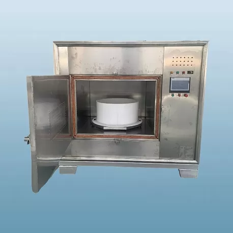
6. Process Scaling and Validation Protocols
Transitioning from benchtop feasibility studies to high-volume production requires a structured scaling methodology. Direct scale-up based solely on volume or weight ratios is rarely successful in dielectric heating applications due to the non-linear relationship between electromagnetic field distribution, material geometry, and dielectric properties as moisture content decreases.
Process validation stages supported by Nasan ensure that laboratory scale dielectric measurements translate accurately to high-volume production. During the initial development phase, engineers map the material's dielectric profile across a spectrum of moisture levels and temperatures. This data informs the design of the pilot system, focusing on power density requirements and belt speed parameters. Subsequent verification stages require checking field leakage, system safety interlocks, and product quality consistency across the entire width of the conveyor belt to ensure that the equipment meets all structural and operational specifications before full integration into the production line.
Operational safety is a mandatory component of the validation process. High-power systems must be equipped with physical attenuators, such as water-loaded choke tunnels at the entry and exit portals of continuous conveyor units, to absorb stray radiation and keep leakage levels well below regulatory limits. These safety boundaries must be monitored continuously with automated detection equipment integrated into the system control architecture.
Frequently Asked Questions
Q1: What parameters dictate the efficiency of microwave drying?
A1: The efficiency is primarily determined by the material's dielectric loss factor, moisture content, sample thickness, and the frequency of the applied electromagnetic field. Water-rich materials absorb energy rapidly, but as the product dries, the loss factor decreases, requiring careful adjustment of the incident power to prevent unnecessary energy waste or localized overheating.
Q2: How does salt content affect the heating behavior of wet products?
A2: Dissolved salts increase the ionic conductivity of a solution, which dramatically raises the loss factor of the material. While this can accelerate the initial heating rate, it can also decrease the penetration depth of the electromagnetic waves, concentrating the energy absorption at the surface and increasing the likelihood of localized thermal runaway if the power distribution is not adjusted accordingly.
Q3: Why do vacuum conditions alter the drying curve compared to atmospheric processing?
A3: Reducing the chamber pressure lowers the boiling point of water, allowing evaporation to occur at much lower temperatures (typically between 30°C and 50°C). This low-temperature boiling prevents the thermal degradation of heat-sensitive compounds, speeds up the internal vapor transport, and minimizes surface crusting or case hardening, which frequently limits drying rates under atmospheric pressure.
Q4: How do equipment designers prevent microwave leakage in continuous systems?
A4: Continuous systems utilize specialized absorption tunnels, known as microwave chokes, at the entry and exit points of the conveyor belt. These tunnels are lined with water-filled tubes or specific absorbent materials designed to suppress and dissipate stray electromagnetic waves, ensuring that any residual leakage remains far below international regulatory standards like those established by OSHA and CE.
Q5: What is the typical operational lifespan of an industrial magnetron?
A5: A standard industrial magnetron has an operational life ranging from 4,000 to 8,000 hours, depending on the quality of the cooling system, power settings, and waveguide maintenance. Implementing robust water-cooling loops and maintaining stable electrical impedance across the system can significantly prolong the operational longevity of these microwave generators.
Industrial Consultation and Inquiry
Integrating advanced dielectric heating into an existing production line requires custom configuration to match your specific material characteristics, throughput targets, and facility layouts. To request a comprehensive feasibility study, obtain pricing for modular processing units, or arrange pilot-scale trials at our testing facility, please contact the Nasan engineering team with your raw material specifications, moisture parameters, and utility constraints.