


Thermal conversion processes are undergoing major changes as industrial operators seek higher thermodynamic efficiency and precise process control. Conventional pyrolysis methods rely on surface-conduction heating, which often results in thermal gradients, processing delays, and uneven product quality. Among these alternatives, microwave pyrolysis offers distinct operational advantages by introducing volumetric heating directly into the core of the processed material. This analysis explores the physics, mechanical configurations, processing bottlenecks, and deployment methodologies of microwave-assisted thermal decomposition, utilizing industrial systems engineered by specialists like Nasan.

Understanding the Dielectric Physics of Microwave Heating
To understand why electromagnetic heating outperforms standard gas-fired or electric resistance heating, one must analyze the dielectric properties of target feedstocks. Conventional heating depends on temperature differentials to drive heat from the outer boundary of a particle to its core. In contrast, electromagnetic processing generates heat internally through molecular excitation.
This molecular interaction is governed by two primary mechanisms: dipole rotation and ionic conduction. When carbonaceous feedstocks are exposed to high-frequency electromagnetic waves, polar molecules (such as water or specific oxygenated compounds) align themselves with the rapidly alternating electric field. At industrial frequencies (typically 915 MHz or 2450 MHz), this alignment field alternates millions of times per second, causing intense molecular friction and immediate volumetric temperature rises.
The efficiency of this conversion is defined by the complex permittivity of the material:
$$\varepsilon = \varepsilon' - i\varepsilon''$$
Where:
$\varepsilon'$ (Dielectric Constant): Measures the ability of the material to store electrical energy from the electromagnetic field.
$\varepsilon''$ (Dielectric Loss Factor): Represents the ability of the material to dissipate that stored energy as thermal energy.
$\tan \delta$ (Loss Tangent): Calculated as $\varepsilon'' / \varepsilon'$. A higher loss tangent indicates a material that heats rapidly under electromagnetic exposure.
Another key parameter is the penetration depth ($D_p$), which determines how deeply the electromagnetic wave can penetrate the material bed before its power drops to $1/e$ of its surface value. The formula for penetration depth is:
$$D_p = \frac{c}{2 \pi f \sqrt{2 \varepsilon'} \left( \sqrt{1 + \left(\frac{\varepsilon''}{\varepsilon'}\right)^2} - 1 \right)^{-1/2}}$$
Because $D_p$ is inversely proportional to frequency ($f$), industrial systems operating at 915 MHz offer significantly greater penetration depths than those operating at 2450 MHz. This makes 915 MHz systems highly suitable for deep-bed bulk material processing.
Key Components in Industrial Microwave Reactors
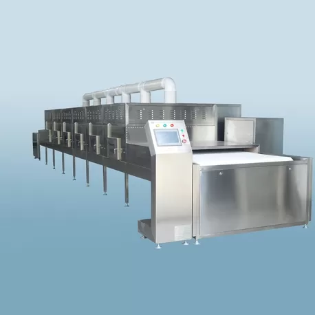
Transitioning from laboratory testing to continuous manufacturing requires robust, heavy-duty hardware capable of handling high power loads while maintaining safe operating conditions.
When optimizing microwave pyrolysis systems, waveguide design is primary. Waveguides are precisely sized metal conduits that transfer electromagnetic energy from the generator to the processing chamber with minimal power loss. For 915 MHz operations, WR975 waveguides are standard, whereas 2450 MHz systems utilize WR340 waveguides.
An industrial system consists of the following subsystems:
The Microwave Generator (Magnetron): High-efficiency, industrial-grade magnetrons, often water-cooled, that produce continuous-wave energy. Power configurations can range from 10 kW units up to multi-megawatt arrays.
The Circulator and Water Load: A passive three-port device that allows energy to travel from the magnetron to the reactor, but diverts any reflected energy back into a water load. This protects the magnetron from damage caused by mismatched impedances or highly reflective processing conditions.
The Tuner (Impedance Matcher): Manual or automated stub tuners that adjust the impedance of the system to match the varying dielectric properties of the material bed as it heats up, ensuring maximum energy transfer.
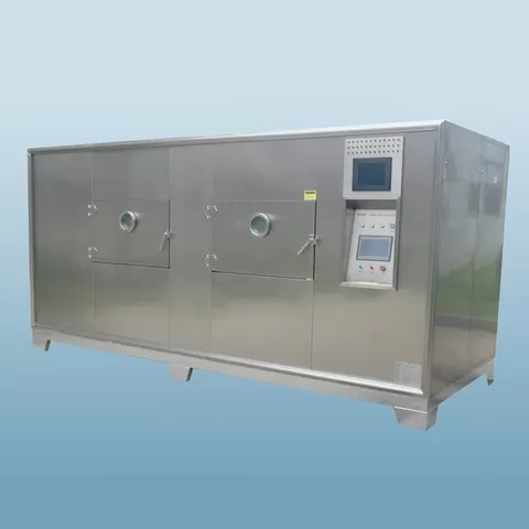
The Applicator (Reactor Vessel): The chamber where the feedstock interacts with the electromagnetic field. These are designed as multimode cavities for bulk processing or single-mode cavities for targeted, high-intensity processing.
Processing Bottlenecks and Mechanical Engineering Solutions
Industrial deployment presents specific physical and mechanical challenges that require advanced engineering solutions.
Managing Thermal Runaway and Hotspots
As carbonaceous materials (such as biochar) heat up, their dielectric loss factor ($\varepsilon''$) often increases. This creates a positive feedback loop: hotter areas of the material absorb more energy, leading to localized melting or uneven product distributions. Engineering organizations like Nasan address this by using mechanical mixing devices, rotary drum reactors, or continuous fluid beds. Constantly moving the material through the electromagnetic field evens out spatial energy distribution, preventing localized thermal runaway.
Mitigating Electric Field Concentration and Arcing
High-power microwave fields can cause electrical discharge (arcing) in the presence of sharp metal edges, carbon dust, or highly conductive materials. If left unmanaged, this arcing can damage the reactor liner and ignite volatile gases. To prevent this, the reactor headspace is purged with a continuous flow of inert gas (typically nitrogen). This sweep gas dilutes volatile organic compounds, removes fine carbon particles from the active field, and maintains a stable dielectric atmosphere inside the chamber.
Feedstock Suitability and the Use of Susceptors
Different materials respond differently to electromagnetic fields, making feedstock preparation a key process step.
Biomass Decomposition Pathways
Lignocellulosic biomass (such as agricultural residues, forestry waste, and nutshells) has moderate dielectric loss parameters. During processing, the bound moisture initially heats up, followed by the rapid decomposition of hemicellulose, cellulose, and lignin. This process produces high-purity syngas (rich in $H_2$ and $CO$) and a highly porous biochar that is well-suited for soil remediation or activated carbon production.
Processing Non-Polar Polymers
Many synthetic polymers, such as polyethylene (PE), polypropylene (PP), and polystyrene (PS), are non-polar. They have extremely low loss tangents, meaning they do not heat up when exposed to electromagnetic waves. Because of this, processing non-polar materials via microwave pyrolysis requires the introduction of a susceptor.
A susceptor is a material with a very high loss tangent (such as biochar, graphite, or silicon carbide) that is mixed with the polymer feedstock. The susceptor absorbs the electromagnetic energy, heats up rapidly, and transfers that heat to the surrounding polymer through conduction. This indirect heating method enables rapid polymer cracking and depolymerization, converting municipal solid waste and sorted plastics into valuable liquid hydrocarbons.
Process Parameter Comparison: Conventional vs. Microwave-Assisted Pyrolysis
The table below highlights the operational differences between conventional thermal processing and electromagnetic-assisted methods:
| Operational Parameter | Conventional Thermal Pyrolysis | Microwave-Assisted Pyrolysis |
|---|---|---|
| Heat Transfer Method | External conduction and convection (outside-in thermal gradient) | Volumetric dielectric heating (inside-out thermal gradient) |
| Heating Rates | Slow to moderate (limited by material thermal conductivity) | Very high (instantaneous molecular response) |
| Thermal Gradient | Hotter at the outer boundary, cooler in the center | Hotter in the core, cooler at the boundary (promotes volatile exit) |
| Startup and Shutdown | High thermal inertia; requires hours of preheating and cooling | Near-instantaneous power control (starts and stops in seconds) |
| Syngas Composition | Higher heavy tar content due to secondary reactions | Higher hydrogen and carbon monoxide content; low tar formation |
| Process Footprint | Large, insulated rotary kilns or fluidized bed complexes | Compact, modular reactor configurations with high energy densities |
The thermal profiles of conventional thermal processing and microwave pyrolysis differ fundamentally. In conventional reactors, volatile gases must travel through a cooler outer layer to exit the particle, which often leads to secondary condensation and undesirable tar formation. In electromagnetic reactors, the core is the hottest zone. This drives volatiles outward through a cooler boundary, reducing secondary reactions and producing a cleaner, higher-quality liquid or gaseous product.
Design Parameters for Continuous Production Systems
Implementing continuous-flow microwave pyrolysis requires robust engineering to prevent energy leakage and maintain a stable internal atmosphere.
A primary design consideration is the feeding and discharge mechanism. Because the reactor operates under anaerobic conditions (without oxygen) and must prevent electromagnetic radiation leakage, standard open feeders cannot be used. Instead, engineers use rotary airlocks and continuous screw conveyors with choke tubes. These choke tubes are designed with specific lengths and diameters relative to the operating frequency, acting as waveguides below cutoff and reducing electromagnetic leakage to safe, non-hazardous levels.
Additionally, the integration of temperature sensors requires careful planning. Standard metallic thermocouples can act as antennas, concentrating the electric field, causing localized arcing, and distorting temperature readings. Consequently, continuous systems rely on non-contact infrared pyrometers or fiber-optic temperature sensors. These fiber-optic sensors are made from non-conductive silica glasses, allowing them to measure temperatures accurately in real-time within high-power electromagnetic fields.
Finally, these integrated systems developed by Nasan ensure process safety through automated PLC control systems. These PLCs monitor forward and reflected power, sweep gas flow rates, reactor pressure, and any electromagnetic leakage around seals. If any metric deviates from safe operational parameters, the system automatically adjusts the magnetron output or initiates a rapid shutdown.

Engineering Consultation and Inquiry
Optimizing an industrial electromagnetic reactor requires a detailed understanding of your specific feedstock's physical and dielectric properties. Our engineering team specializes in custom-designing industrial-scale systems tailored to your throughput, moisture content, and product yield requirements.
To help us evaluate your process, please provide details on your feedstocks, required throughput rates, and targeted output specifications. We can collaborate with your team to conduct dielectric testing, run pilot-scale trials, and design a custom, high-efficiency continuous processing system.
Contact our engineering division today to discuss your project requirements and request a technical proposal.
Frequently Asked Questions
Q1: What is the main difference between 915 MHz and 2450 MHz frequencies in microwave systems?
A1: The primary differences are wave penetration depth and power capacity. Systems operating at 915 MHz offer a much greater penetration depth, making them suitable for large-volume industrial material beds. They are also available in higher power outputs per single magnetron (up to 100 kW or more). Systems operating at 2450 MHz have a shallower penetration depth and are typically used for thinner material beds, laboratory testing, or small-scale processing.
Q2: How do you prevent microwave leakage at the feed and discharge ports?
A2: Leakage is prevented by using metallic choke structures and wave-attenuating transition zones. These components are designed so their physical dimensions act as waveguides below cutoff for the specific operating frequency. This keeps electromagnetic fields confined to the heating chamber while allowing materials to flow continuously through rotary airlocks or screw conveyors.
Q3: Can materials with high moisture content be processed directly?
A3: Yes, water has a very high loss factor and absorbs electromagnetic energy rapidly, making it easy to heat. However, processing feedstocks with high moisture content requires a two-stage approach. In the first stage, energy is used to evaporate the water. In the second stage, once the material is dry, temperatures rise to the levels required for thermal cracking. Integrating a pre-drying step can significantly improve overall system efficiency.
Q4: Why is nitrogen sweep gas necessary during the heating cycle?
A4: Nitrogen serves two key purposes. First, it displaces oxygen to maintain the anaerobic environment required for pyrolysis. Second, it sweeps volatile gases and fine carbon dust out of the active heating zone. This rapid removal prevents high-voltage gradients from forming in the headspace, which eliminates the potential for electrical arcing and plasma formation.
Q5: What parameters must be provided to design a custom industrial reactor?
A5: To design an efficient system, our engineers require details on the feedstock type, average moisture content, particle size distribution, and target throughput (kg/h). We also need to know your target output ratios (biochar, bio-oil, or syngas) so we can configure the appropriate power levels, residence times, and condensation systems.

