Industrial drying operations face persistent trade-offs between throughput, product quality, and energy consumption. vacuum microwave drying addresses these constraints by combining reduced-pressure environments with volumetric heating. This article examines the physical mechanisms, equipment configurations, and application parameters that define effective vacuum microwave drying systems, providing a framework for process engineers evaluating this technology.
The process operates on two simultaneous principles: microwave energy penetrates the material bulk, converting to heat through dielectric loss, while vacuum conditions lower the boiling point of moisture, enabling evaporation at reduced temperatures. This synergy allows drying of heat-sensitive compounds that would degrade under conventional hot-air or steam methods.
Microwave frequencies—typically 915 MHz or 2450 MHz—couple with polar molecules, primarily water, causing rapid molecular rotation. The heating pattern is volumetric, not surface-conducted. This means thermal energy generates throughout the material cross-section, driving moisture from interior regions toward the surface. The vapor pressure gradient complements the temperature gradient, accelerating mass transfer.
Vacuum application modifies the thermodynamic path. At absolute pressures between 10 and 100 mbar, water evaporates at 20–40°C instead of 100°C. This low-temperature regime preserves thermolabile constituents, including enzymes, vitamins, and aromatic compounds. The combination produces dried products with retained structural integrity and rehydration characteristics superior to those from convective or freeze-drying methods.
Conventional drying loses significant energy to heating the drying medium (air or steam) and to sensible heat of the substrate. Microwave energy converts directly to internal heat, with conversion efficiencies above 70% for most moisture-containing materials. The vacuum enclosure reduces convective heat losses and eliminates the need for high-volume air handling. These factors contribute to shorter processing times—often 50–70% less than equivalent convective drying cycles.
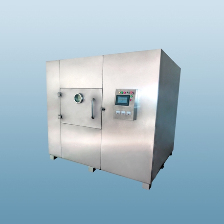
Industrial vacuum microwave drying installations comprise several integrated subsystems. Each component influences the overall performance, reliability, and product consistency.
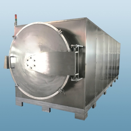
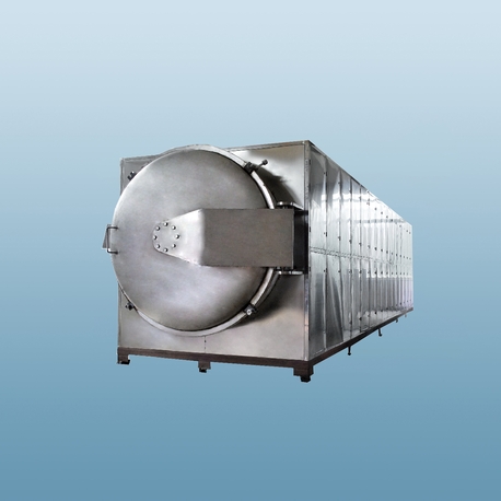
The drying vessel must withstand external atmospheric pressure while containing microwave radiation. Chambers are constructed from stainless steel or aluminum, with internal dimensions matching the required batch size or continuous throughput. Microwave generators—magnetrons or solid-state sources—deliver power through waveguides or coaxial applicators. Power distribution across the chamber requires careful design to avoid hot spots, which cause localized overheating and product degradation. Mode stirrers or rotating turntables help homogenize the electromagnetic field.
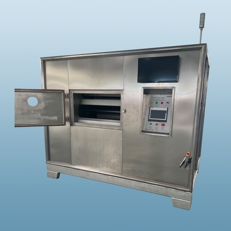
For batch systems, the chamber includes loading doors and vacuum seals that maintain integrity through repeated cycles. Continuous systems employ vacuum locks or rotary valves that allow product entry and exit without breaking vacuum. The choice between batch and continuous configurations depends on production capacity and product handling characteristics.
Vacuum pumps maintain the required pressure level. Rotary vane pumps, dry screw pumps, or roots blowers operate in sequence to achieve the target vacuum. The extracted vapor contains water and volatile compounds. A condenser—often a shell-and-tube or plate-type heat exchanger—cools the vapor stream, recovering latent heat and reducing the load on the vacuum pump. Condensate collection provides a measure of moisture removal rate, useful for process monitoring.
Pressure control systems regulate vacuum level through variable-speed drives or bypass valves. Precise pressure management affects both drying rate and product temperature, as lower pressures shift the evaporation curve. Operators adjust pressure setpoints based on product moisture content and thermal sensitivity.
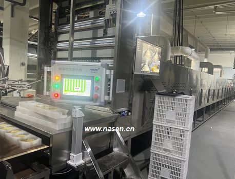
Process control integrates multiple sensors: thermocouples or infrared pyrometers measure product temperature; capacitance or microwave-based sensors track residual moisture; pressure transducers monitor vacuum integrity. Programmable logic controllers (PLCs) execute drying recipes that sequence power application, vacuum ramps, and cooling phases. Data logging enables traceability and process optimization. Modern systems include remote access for diagnostics and recipe management.
Vacuum microwave drying finds application across sectors where product quality commands priority. The following categories illustrate typical use cases.
Pharmaceutical intermediates and APIs: Active pharmaceutical ingredients often exhibit thermal instability. Vacuum microwave drying reduces exposure to elevated temperatures, preserving crystalline structure and polymorphic form. The closed system prevents contamination and allows solvent recovery.
Food ingredients and nutraceuticals: Fruit powders, vegetable extracts, and probiotic cultures retain color, flavor, and biological activity. The rapid drying minimizes oxidative degradation, and the absence of high-temperature air flow prevents surface hardening.
Chemical catalysts and fine chemicals: Porous materials such as zeolites, activated carbon, and supported catalysts benefit from uniform moisture removal without pore collapse. The drying profile can be tailored to avoid cracking or shrinkage.
Wood and agricultural products: Timber drying with vacuum microwave reduces checking and warping compared to kiln drying. Grain and seed drying maintains germination rates by avoiding thermal stress.
Effective application of vacuum microwave drying requires systematic determination of key variables. These parameters are interdependent and must be optimized for each product.
Microwave power density: Expressed as watts per kilogram of wet material. Typical ranges are 1–5 W/g, with higher densities reducing cycle time but increasing the risk of thermal runaway. Power density selection considers the dielectric loss factor of the material, which varies with moisture content and temperature.
Vacuum level profile: Stepwise pressure reduction prevents boiling-induced foaming or splattering. Initial drying at higher pressure (50–80 mbar) removes surface moisture, then lower pressure (10–20 mbar) drives internal diffusion. Pressure ramping rates are adjusted based on vapor generation rate.
Product loading and layer thickness: Microwave penetration depth limits the effective bed thickness. For most organic materials, penetration depth at 2450 MHz is 2–5 cm. Loading beyond this depth results in uneven heating, with the core remaining wet while the surface overheats. Tray designs or continuous belts accommodate layer thickness control.
Endpoint detection: Drying completion is indicated by plateauing of the product temperature or by stabilized vacuum pressure (indicating no further vapor generation). Dielectric properties change with moisture content, so some systems use microwave transmission or reflection measurements for real-time moisture estimation.
Each parameter interacts with material properties—density, thermal conductivity, dielectric constant, and specific heat—requiring pilot-scale trials for new products. Equipment suppliers typically offer test facilities where process conditions are validated before full-scale equipment fabrication.
Sustained performance of vacuum microwave dryers depends on attentive operation and scheduled upkeep. Key areas include:
Microwave leakage monitoring: Regulatory limits for microwave radiation (5 mW/cm² at 5 cm from the surface) require periodic checks of door seals, waveguide joints, and viewing windows. Leakage detectors verify compliance during operation.
Vacuum seal integrity: Door gaskets and shaft seals degrade with temperature cycles. Visual inspection and leak-down tests (rate of pressure rise after pump isolation) indicate seal condition. Replacement schedules based on cycle count prevent unplanned downtime.
Condenser performance: Cooling water temperature and flow rate affect condensation efficiency. Fouling of heat exchanger surfaces reduces heat transfer; cleaning intervals depend on the nature of volatiles and particulate carryover.
Generator maintenance: Magnetron life is influenced by operating hours and cooling adequacy. Cooling air filters and water jackets require regular cleaning. Solid-state generators offer longer maintenance intervals but higher initial cost.
HANNA, through its drying equipment division, provides comprehensive service packages that include annual performance audits and spare parts kits tailored to each installation. Nasan dryers incorporate predictive maintenance alerts within their control software, notifying operators of pending service actions based on runtime and cycle counts.
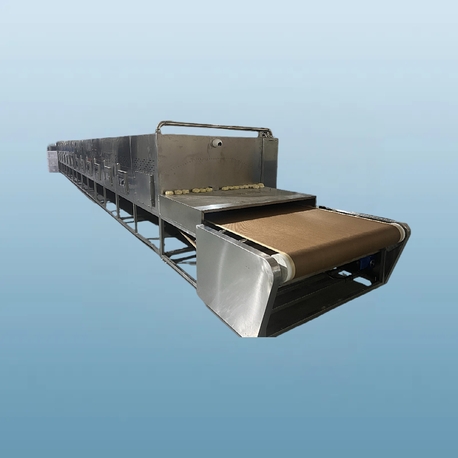
Transitioning from pilot to production scale involves engineering choices that affect footprint, utilities, and workflow. Batch dryers suit low- to medium-capacity operations with frequent product changes. Continuous dryers—using belt or screw conveyors—handle higher throughput and integrate with upstream and downstream equipment.
Utility requirements include three-phase electrical supply for microwave generators, cooling water for condensers and magnetrons, and compressed air for control valves. Steam or hot water may be needed for auxiliary heating of the chamber walls to prevent condensation. The total installed power ranges from 20 kW for small batch units to over 500 kW for large continuous lines.
Integration with material handling systems—such as vacuum loading of wet product and pneumatic conveying of dried powder—requires attention to dust containment and explosion protection, particularly for organic materials. Nasan provides interface engineering for integration with existing conveying, milling, and packaging lines, ensuring smooth material flow without cross-contamination.
Q1: What materials are unsuitable for vacuum microwave drying?
A1: Materials with very low dielectric loss factors, such as pure metals or highly
non-polar polymers, absorb minimal microwave energy and do not heat effectively.
Additives or moisture content above 5% generally provide sufficient coupling.
Materials that outgas excessive volatiles under vacuum—especially corrosive or
flammable solvents—require specialized containment and inerting systems.
Q2: How does vacuum microwave drying compare to freeze drying?
A2: Freeze drying (lyophilization) operates at sub-zero temperatures and relies on
sublimation, which is slower and more energy-intensive. Vacuum microwave drying
maintains higher product temperatures (typically 20–60°C) and shorter cycles.
Product structure differs: freeze-dried materials are often more porous, while
microwave-dried materials show denser structure but retain comparable
rehydration ratios for most food and pharmaceutical applications.
Q3: Can vacuum microwave drying achieve continuous operation?
A3: Yes, continuous designs use vacuum locks or rotary feeders to introduce and
discharge material while maintaining chamber pressure. Belt-type continuous
dryers spread material in a thin layer, passing through multiple microwave
application zones. These systems suit high-capacity production of uniform
materials, such as snack foods or catalyst beads.
Q4: What safety measures are required for vacuum microwave drying equipment?
A4: Primary
safety features include microwave leakage interlocks that shut down generators
if chamber doors are opened, pressure relief vents to prevent implosion, and
thermal sensors to prevent runaway heating. For flammable solvents, inert gas
purging and explosion-proof electrical components are mandatory. Compliance with
regional standards (e.g., CE, UL, or GB) is verified during installation.
Q5: How is drying uniformity assured in large chambers?
A5: Uniformity is achieved through multiple microwave feeds, mode stirrers that
rotate the field pattern, and moving product beds (turrets or vibrating
conveyors). Finite element modeling during design phase optimizes applicator
geometry. Post-installation, heat map tests using temperature-sensitive markers
confirm field distribution.
Q6: What is the typical moisture reduction capacity per cycle?
A6: Capacity depends on power input and material properties. A 50 kW batch unit can
remove 40–60 kg of water per hour under typical conditions. Continuous systems
scale linearly with belt width and speed. Specific rates are established during
pilot testing, as material characteristics influence evaporation efficiency.
For detailed process evaluation, equipment sizing, or pilot testing arrangements, direct inquiries to the engineering group at Nasan. The company's application laboratory offers material testing services to determine optimal drying curves and to validate product quality metrics before capital commitment.